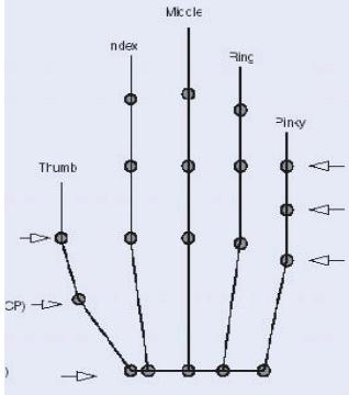
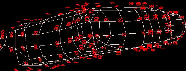
fig. 8 Index finger with numbering for each vertex
Still, we had to go further: every finger is divided into
three parts. For example, the thumb base part can be illustrated in different
visual pattens in fig. 9 and fig. 10. Those different displaying
patterns can greatly help us find which vertices best represent the edge
vertices between adjacent parts. For example, in fig. 9, vertex 20
should not be the edge vertex and we should create a polygon composed of
vertices 20, 24, 21 (right-hand rule in OpenGL rendering).
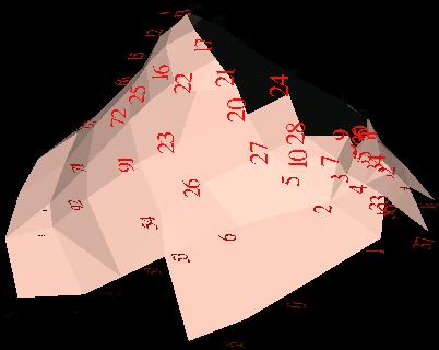
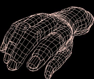
fig. 9 Polygon representation of thumb base with vertex-numbering
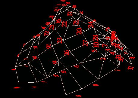
fig. 10. Thumb base with vertex-numbering in hidden lines
Now comes the most tedious and time-consuming work. For each part (except
the thumb base part), we computed its weight center, the part's direction,
the flexion centers and axes and the abduction centers and axes if
applicable. Because our original hand gesture is the very starting
gesture pattern, a part's flexion and abduction each have two centers and
rotation axes: positive and negative directions. Sometimes, the negative
direction can not be obtained by multiplying the positive one by minus one.
To test the effect, a simple but effective animation program must be written.
At this step, normals are not calculated. To get a better performance,
we have to cut of some vertices of a part and to attach some (or all) of
them to the adjacent part. As for the thumb base part, additional
work is needed: for example, we have to move some vertices to new places.
Although the new place is very close to the old one, it gives better performance
and outlook.
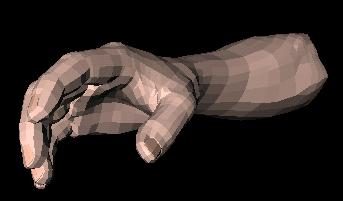
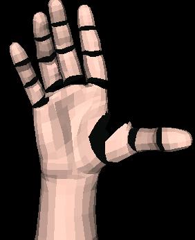
After all joints flexion/abduction centers and axes are determined, we
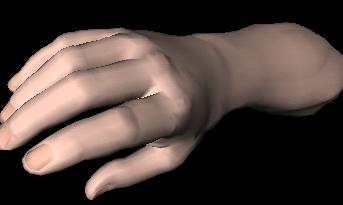
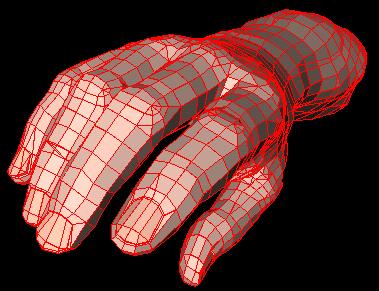
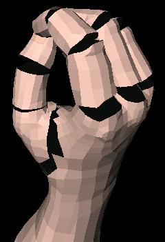
can make our virtual hand to express a certain set of gestures. Fig.
11 shows a full stretched hand, and fig. 12 displays somewhat bent
(cup-shaped) hand. Please note there are holes when the virtual hand makes
gestures.
fig. 11 A full stretched virtual hand
fig. 12 A cup-shaped virtual hand
From division to integration
In the above section, we have disintegrated the whole hand into seventeen
parts and calculated the necessary parameters such as flexion/abduction
center, axis, thus producing fifteen holes in the hand. In this section
we discuss how to fill those holes with fifteen patches. It should be remembered
that some of the patches (that made up the two upper holes of the four fingers
and one upper hole of the thumb) get involved in only one operation: flexion,
while other patches in two operations: both flexion and abduction.
Linear interpolation does not work: the bending movement gives a circular
trajectory and the side-to-side movement does nearly so. We have to calculate
the 3-D vertices on the convex trajetories for the flexion and abduction
movements. And we must dynamically compute those points as we have to consider
the hand animation, which produces unpredictable gestures.
At this step, normals both for the seventeen parts and for the fifteen
patches must be applied.
Another thing that should be noted is the Inventor's animation mechanism
which is different from the OpenGL's: in OpenGL we can manipulate every
vertex/normal in nearly every step through the operation on the display
list, while in Open Inventor we can not do this because the all the vertices
and normals consisting of a part are considered as one unit. For example,
after providing the initial vertices normals, and transformation (rotation,
displacement...) parameters of a part, Inventer automatically renders following
these specifications. And during the rendering process changes of those
parameters in user's program does not have any effect on the rendering.
The question becomes how to combine the automatic animation rendering
of seventeen parts by Open Inventor with the dynamical rendering
of the fifteen patches by the programmer.
To solve the above problems we extended the Open Inventor's engine class
group by adding two new engine classes into Open Inventor. One for the thumb
base patch and the other one for the remaining fourteen patches. The two
classes complete the interpolation of the patch vertices and normals
with two different algorithms. One concerns with combined rotation computation,
the other the combination of linear with circular rotation for the thumb
base patch which needs to be further improved in the future. The algorithm
is that with the edge vertices of a part as a set of starting vertices, the
flexion/abduction (rotation) centers and axes as constants, a set of interpolated
vertices can be calculated according to the given flexion/abduction (rotation)
angles. The normals of the interpolated vertices can be computed from the
vertices. The Inventor's matrix operation functions have been used for
the vertex/normal calculation and it should be noted that vertex and normal,
though they each are represented as a vector, use different vector/matrix
operations in transformation process. The flexion/abduction transformation
order applied in the Inventor (OpenGL) rendering for any one of the seventeen
parts should be applied reversely in the calculation of the corresponding
patch interpolation vertices. The normals for the adjacent vertices (those
vertices that are shared by the part and patch) take the value of the normals
in the part not the value computed in the patch, because the normal for a
single vertex is a single value and we can not change the normal value in
the part.
With the implementation and integration of the two classes, we have very
good results, for example: fig. 13 shows our new virtual hand when nearly
stretched from front view while fig. 14 the cup-shaped new virtual
hand from back view.
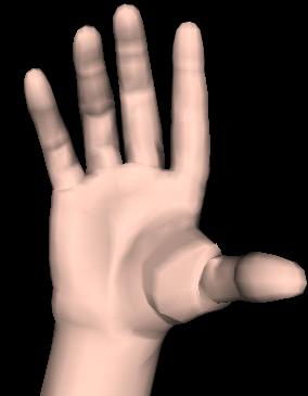
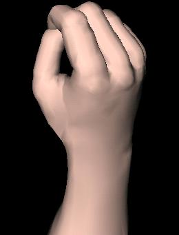
fig. 13. New stretched virtual hand
fig. 14 New
cup-shaped virtual hand
Program design
The virtual hand is implemented with C++ programming language and the Open
Inventor which is also object-oriented API. This object-oriented feature in
the programming language and API is fully utilized in the construction of
hand model and animation. As above said, a hand is composed of seventeen parts
(objects): forearm, palm, and three parts for each finger (including thumb).
Although those seventeen parts look different in the physical world, they
share the common characteristics. For example:
- they are all composed of 3-D vertices with normals and colors;
- they have same rendering mechanism;
- each has flexion and abduction movement, though some parts show zero
abduction;
- built-in timing engines (for flexion and abduction) can be inserted
into each part for gesture display and animation;
- each part, when moving, leaves a hole, which has be to filled with
a patch;
- we have to calculate for every part its weight center, direction,
and transformation parameters;
- each part should provide functions that can be used to update its
edge specification, for example, insert new edge vertices and/or cut off
the old ones;
- instances for creating the patch vertices/normals are substantiated
from the above-mentioned newly-inserted engine classes;
- once the vertices/normals for the patch that attaches to the part
are created, this part will provide a rendering mechanism.
Naturally, a single class can fulfil those requirements and we call it
XFinger.
Similarly, a
Finger class is written to:
- set up three objects (parts) for a finger;
- attach each of the three patches to its corresponding part;
- render these parts and patches in correct order;
- provide some functions for controlling the XFinger objects.
Finally, a
Hand class will:
- create five Finger instances: thumb, index, middle, ring and pinky;
- set up two XFinger objects: palm and forearm;
- provide functions for setting up the edges for all the seventeen parts;
- provide necessary information for calculating the edges, transfomation
parameters for all the parts;
- connect palm and its patch;
- control the animation and/or gesture displaying;
- read/write hand information from/to files;
- most of all, create thumb base patch;
- render all the fingers and the other objects in correct order.
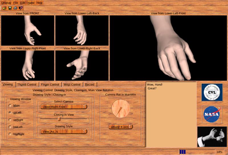
GUI Design
We used Qt 3.0.5 to implement the virtual hand visualization. One of Coin's
API, SoQt, provides a very good application interface between Qt and Open
Inventor. Thus all the hand rendering can be transferred into a Qt widget
for visual display. In our system we use the QLabel as displaying widget.
In the following we will not dicuss the program design, but will introduce
the features of V-Hand in a way of looking through V-Hand user manual.
There are four regions in addition to the traditional menu bar, toolbar
and status bar:
- The display part: it occupies the upper half which is made of a main
viewing part and four small parts. Hand images can be displayed from
different view directions.
- The control part: the lower left region, composed of five tab widgets.
Here we can control hand, camera parameters and image recording process.
- Multiple rich text output region: the lower middle part. It provide
an immediate information about the hand, camera.
- Logos: the lower right region.
Outlook
- There are many different outlooks (for example, Window-style, SGI-style)
to choose from the menu "display" or corresponding control keys;
- Animation can be controlled from "Hand" menu or control keys;
- A natural hand or a color hand can be chosen from "Hand" menu or control
key.
Fig. 15 is just one example.. We will show different outlooks while we introduce
other features.
fig. 15 One of the many V-Hand
display styles
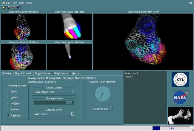
Viewing
Using the "Viewing" tab, we can:
- choose for every displaying region the viewing direction (we have
eight fixed cameras and one moving camera to choose from);
- magnify or increase the displayed image;
- control the moving camera to look at the hand from any direction in
3-D world;
- and choose drawing style for the virtual hand.
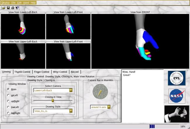
Fig. 16 show one example of the viewing styles: the main viewing window
displays a magnified hand drawn in colored lines from the lower-right-front
camera view, up right window with magnified colored hand (normals applied)
from lower-left-front camera view ......
fig. 16 One of V-Hand viewing styles
Thumb control
Fig. 17 is the thumb control tab used for controlling thumb joint's flexion
and abduction rotations. "DIP", "PIP", "MCP" indicate the upper, middle and
base parts of thumb, and "A", "F" means abduction and flexion rotation degrees.
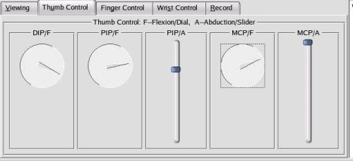
fig. 17 Thumb control tab
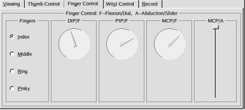
Finger control
The other four fingers' gestures can also controlled by modifying their
joints' flexion/abduction angles, as is shown in fig. 18.
fig. 18 Finger control tab
Wrist control
Wrist's movement is a little different, because there is displacement in
3-D world ("Tr-X/Y/Z"). And in addition to the flexion (Bend) and abduction
(Side-to-Side movement), there is third one: the "Twist" movement.
All these movements can controlled as shown in fig. 19.
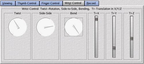
fig. 19 Wrist control tab
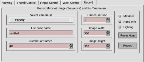
Record image control
With this control tab, we can record a sequence of hand images in accurate
fixed time sequence by:
- selecting any of the nine cameras or all the eight fixed or nine cameras;
- setting up number of frames for the image sequence;
- giving image size (width and height);
- defining recording speed (frames per second) for storing images for
a movie;
- writing down hand parameters (rotation angles for every joints);
- storing hand animation/gesture transformation parameters and camera
specifications: rotation matrices, virtual hand (box) size, etc for
hand gesture recognition, analysis, and tracking;
- adding lighting or delete lighting;
- reset hand to initial position, and then recording;
- image file name is in the format: "baseFileName.nnn.mmmmmm.(RGB/mat/ang)":
baseFileName is inputted by user, nnn represents camera, mmmmmm is the frame
number, RGB is image file in RGB format, mat the matrix file, and ang gives
the hand parameters.
Fig. 20 tells how set up these parameters for recording a (movie) sequence
of images.
fig. 20 Image recording control tab
When in the recording process, a progress bar in the status bar will report
the recording progress in real time. Fig. 21 to fig. 28 are 8 images
(one frame) from eight fixed cameras:
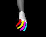
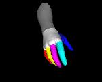
fig. 21 lower-left-back view
fig. 22. lower-left-front view

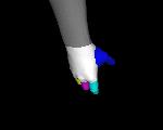
fig. 23 upper-left-back view
fig. 24 upper-left-front view
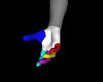
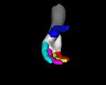
fig. 25. lower-right-back view
fig. 26 lower-right-front
view
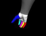
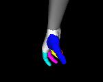
fig. 27 upper-right-back view
fig. 28 upper-right-front view
Future Work:
We are now working (will soon work) on the V-Hand in several categories:
- set up hand constraits on the hand animation / gestures;
- find a better algorithm for thumb base patch vertices calculation;
- create interpretation messages for V-Hand GUI package (status bar
infomation, "what's " information, and "Tips" prompt information;
- show the recorded images and try to make a movie on these images;
- display voxel images of the hand;
- work on the inverse kinematics problems.